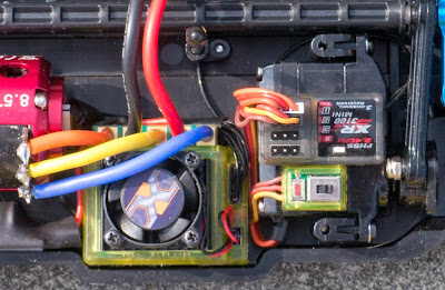
Most servos and speed controllers come with a wire that is too long for the average RC car. The usual way to deal with this is to either make a spiral by tightly wrapping the wire around a pencil, or by carefully bundling the wire up and securing it with a zip-tie.
A better way, albeit requiring more effort, is to shorten the servo wire to the exact length needed. The unused length of wire is just ballast, and also restricts current flow.
This post shows you how to shorten servo wires.
WARNING: This and other DIY projects are purely "at your own risk". If you are at all uncomfortable or inexperienced working with electronics, please reconsider doing the job yourself.
One method of shortening the cable would be to replace the connector. This works fine, but I found it is actually easier to shorten the cable inside the servo. Crimping the tiny servo connectors is tricky at best and leads to failure if not done 100% right.
First, measure the exact length of wire you need and add 1 cm or so to compensate for the amount of wire that resides within the servo case.
Open up the servo. Usually there are four long screws, accessible from the bottom, that hold the servo together. Ensure that you don't take off the top cover, otherwise all the gears may fall out.
There are several construction types of the servo electronics. In the photo above we have a tiny PCB (circuit board) that floats in the servo case, just held in place by all the wiring. Sometimes you have a PCB that covers the whole surface and is directly soldered onto the motor. Other times the PCB is soldered onto the potentiometer.
At this point study your particular servo and how you will approach changing the wire. In the example servo it is very easy to change the wires. But on some servos you may have to unsolder the potentiometer, which may be difficult. If you are not comfortable at this stage because of your servos construction, simply put the servo back together and keep the long wire. No point risking damage to an expensive item.
Take note of where the different colored cable leads connect to. Every servo is different. The simplest way is to make a photo for later reference.
Before you cut the wire at the point you marked earlier, slide the rubber grommet that feeds the wire into the servo case past the point where you intend to cut the wire.
Now comes the point of no return: cut the wire!
Cut the remaining piece of wire that is still soldered to the servo close to the circuit board. We do this so that we can unsolder each wire separately from the PCB, which makes this job much easier.
With the old wires removed, the solder pads can be cleaned up. Strip the new wire and tin it with fresh solder.
Solder the new wire back in place. Ensure that the color coding and the way of how the wires connect to the pad is exactly the same as it was originally.
Put the servo back together and test it. The whole process does not take more than 10 minutes.
If you want to use the servo later in another car where you need a longer cable, you can simply do the procedure again using a new servo cable cut from an inexpensive servo extension lead.
The same method can be applied on ESC, both servo wires and switch wires as can be seen in the Tamiya TT-02 photo above.
Happy RC-ing!


This is great. After reading, I don't know why i wasn't thinking from "inside the box"! PS: FIRST
ReplyDelete